What’s in a mill… Saturday, Mar 31 2012 

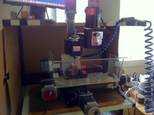
My mill.. not quite perfect as it is :-)

My mill.. not quite perfect as it is 🙂


Due to popular demand, another blog post!!! (well ok, a couple of people asked me about this)

When I bought my milling machine, I was limited largely by the amount of money I had to spend, my understanding of what I wanted to do, and my limited (at the time) understanding of what different mills were capable of doing.

I will try and break this down in to a few basic criteria, though ideally a workshop would have multiple machines with each one appropriately tasked. The key to this is knowing what each machine is capable of, and what is needed for each operation required..

as an example, for making a mainplate, ideally you need something that is capable of accurately pointing/drilling the holes for all of the jewels, screws, pins etc, as well as a machine for milling all of the recesses for the wheels, levers etc.. for making wheels and pinions a rigid machine that has precise angles and indexing capability (the ability to rotate a precise angle to form the right number of teeth on each wheel and pinion) and also able to hold the correct cutters.

At the time I believed the Sherline could fill all these requirements and more!! I opted for a CNC version as I have a decent understanding of electronics, and liked the idea of programming it and letting it rip!!  With around 7 years of tinkering with the mill I have a much greater understanding of what the machine is capable of, and while with a large amount of work it could perform all the duties I want of it, it would probably not be worth it in the long run.

Given an unlimited (or at least very large) amount of money, I would purchase 3 separate machines (and somewhere to put them all)

Machine No 1 – For precise placement of holes – A Hauser M1 jig borer, with the ability to co-ordinate drill holes to within 1/1000 of a mm, can’t get much better than this, though largely used as decorations in workshops…

http://www.lathes.co.uk/hauser/page4.html

Machine No 2 – For general milling operations – A Haas CNC Mini Milling station, fast milling speed, 10 tool changer… whats not to like.. apart from the price tag…

http://www.haascnc.com/mt_spec1.asp?id=SMINIMILL&webID=MINI_MILL_VMC

Machine No 3 – For wheel and pinion cutting – An Aciera F1, super precise, rigid as anything, made for doing this.. or a Dixi, unfortunately the dixi hasn’t been made for over a decade, and the Aciera is still quite expensive.. but they would round out any workshop superbly…

http://www.lathes.co.uk/aciera/
Of course the mill is only part of the equation, ideally a number of lathes would also be desired for the ideal workshop, notably a Schaublin 70.. using this for all turning operations, items can be transferred between this and at least the Aciera, as they share the same tooling..

The ideal milling machine is incredibly rigid, so that even at the extremes of its travels there is no flexing of the mill axes, which would create inaccuracies in the process.

The other main quality required for a good mill is accurate leadscrews, these are the parts of the mill that provide the movement of the axes, these need to be smooth running so that they don’t bind which would create jerky cuts.. and there also needs to be no slop or play in the threads, as this would change the repeatability.. you need to be able to move an axis forward and back, and have it return to the same place each time, this is what will add the most value (and cost) to a machine. most machines use a standard V cut thread to accomplish this, but on high end CNC machines this is replaced with a “ballscrew”

My sherline has issues in both of these departments, it is largely made of aluminium, which has (for something made of metal) a larger amount of flexibility than cast iron or steel, as well as this the way the spindle is mounted has its own issues as well… There are now ballscrew kits available for my mill, though the cost is fairly prohibitive given the initial cost of the mill..

At the end of all this, the milling machine I have is the best I could get for the money I have spent on it, and the things I have learnt while using it will stand me in good stead for when I am able to afford my ideal trio..
It’s alive!! and a bit of a monster… Wednesday, Jan 4 2012 

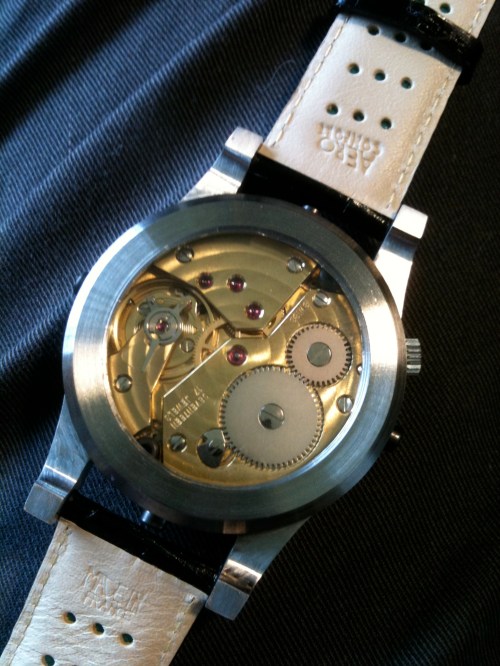
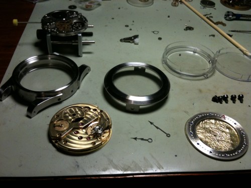
After a quick clean of all of the bits, the movement ticks along nicely, all I need to do is fit the dial and hands to the movement, then this group into the case and figure out how to hold it all tight..

To attach the dial to the movement with the least possible fuss, I line up the crown on the movement and case, and use rodico (watchmakers blu-tac) to get the dial as close to upright as possible.

Once I get it as close as I can, I drill 2 holes through the already existing holes in the dial through to the movement, and place 2 screws through to hold the dial in place, when I test the movement/dial into the case it is thicker than I can use, so the gold layer has to be removed, this lets the register ring sit flat against the movement.

For holding the whole assembly into the case, I enlarge the holes normally used for the casing screws, and fit 2 of the bolts that I use to hold the case together as casing screws… a little bigger than normal, but they seem to do the job 😉

A quick clean up of any debris that got where it shouldn’t, all the screws checked a few times, and the movement is secured in snugly. I fit the case back, loctite all of the case bolts, another quick look… Undo all the bolts, remove the case back and the hair that had slipped in, repeat the process a couple of times, and the watch is basically done!

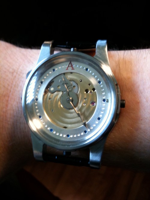
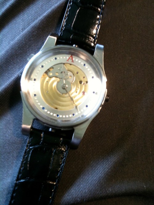
I fit the band and try it on.. not too bad.. though a little larger than I’m used to for sure 😉

A1 Front

A1 Front

A1 Back

A1 Back

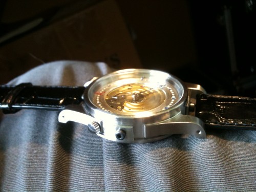
A1 Side

A1 Side

And on the wrist!!

And on the wrist!!

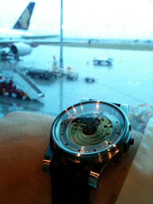
So after a whirlwind 7 weeks of machining, filing, scattered with the flu, dentists appointments, as well as a full time day job, my watch is ready to fly off to foreign climes 😉

A1 ready to fly

A1 ready to fly

Stay tuned for A2……

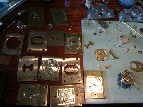
and here’s a quick shot of all of the brass that was machined in the process, as well as the prototype (as far as it got) sooo many brass filings to clean up…

All up about 2kg of brass

All up about 2kg of brass

Swirly? Tuesday, Nov 22 2011 

OK,

Case,  Check

Dial,  Check

Hands, Check

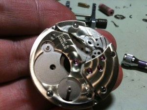
Movement…. not so check.. I can’t put one of the bare non-decorated ETA movements in to this piece, I figure either geneva stripes or a spotted pattern would work nicely.  Having experimented with these patterning methods, I know that I will either have to use an abrasive material impregnated tool, or something like a piece of wood charged with an abrasive like diamond paste or similar, and I do have some silicon polishing bits that should fit the bill nicely.

To do Geneva stripes the movement plates have to be held in a vice that can slide backwards and forwards in  straight line, while applying pressure with the abrasive, for this there are dedicated machines available, though I don’t know if any of these are located in Australia, and I certainly couldn’t get one fast enough anyway.

I had previously experimented doing striping with a large milling machine and discovered that for the best results I needed to be able to control the pressure placed on the abrasive, milling machines don’t do this well.. A drill press would work nicely for this, but I don’t actually have one, not helpful..

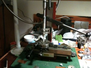
I was able to jury rig up a combination of a jewellers hand piece (for drilling etc) attached using a variety of bits and pieces to a dial stamping machine, this machine has a sliding base, with a spring loaded handle to control the pressure, while my foot controls the speed of rotation.. Still not the ideal machine, but should work for one set of plates at least..

Machine of many parts

Machine of many parts

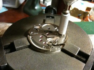
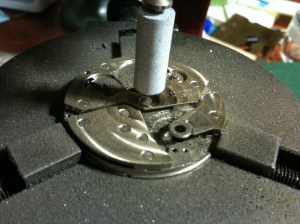
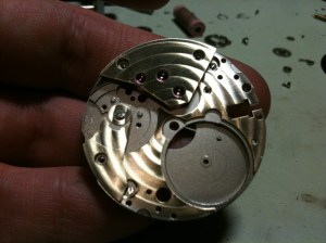
I place the plates where the dial would normally sit and do a few test stripes, but can’t make it all the way across the movement before I run out of room to move.. Unperturbed I turn the dial holding platform allowing me to do circular Cote de Geneve! with a few tests I get a pattern that looks good, and is repeated on the mainplate front and back, and the top of the bridges.

Round and round we go

Round and round we go

Where we stop,

Where we stop,

About here looks good

About here looks good

As the abrasive has ground off the rhodium plating that was coating the movement, leaving it a little messy..

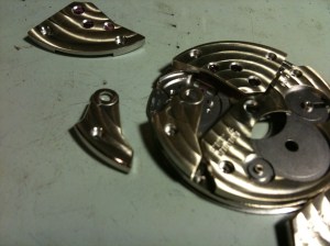
All the bridges, freshly ground, plus a few spare...

All the bridges, freshly ground, plus a few spare...

A quick trip to the platers and it looks all golden and new (well mostly, theres a couple of spots that don’t look 100% but they’re mostly in spots that are not seen)

Freshly plated, ready to put back together

Freshly plated, ready to put back together

The movement is re-assembled and set back to ticking!

All the bits and pieces, ready to make into a watch!

All the bits and pieces, ready to make into a watch!

Many hands…. and a Pretty Face Sunday, Oct 30 2011 

The design brief I gave myself for the hands and dial of the watch were fairly straight forward, I wanted it to be easily readable, while being a bit “special”.

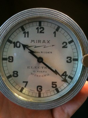
The hand design was basically set as soon as I saw this clock, all that I had to do was reduce the size, and decide on the material to be used.

The inspiration for my hands

The inspiration for my hands

I started by taking a picture of the clock as perpendicular as I could, then importing that into my CAD program, I traced around the hands, and adjusted a few lines to make it look a little smoother. I then reduced the overall size of the hands proportionally so that the very tip of the minute hand would touch the centre of all of the markings on the chapter ring.

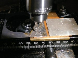
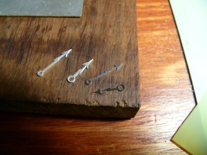
I cut the outline of the hands out using my CNC mill. Just in case, I cut one set out of Titanium, and another pair out of sterling silver.

Cutting the hands

Cutting the hands

Silver and Titanium hands - Pre-polishing

Silver and Titanium hands - Pre-polishing

Just looking at the 2 sets side by side, the silver ones are way too thick, I file the rough edges off the titanium set, and do a quick polish of the hands to almost a black polish. While I’d like to anodise these to a nice blue, I am running out of time and if I wreck this set I won’t have the time to re-finish this set.

Titanium Hands

Titanium Hands- pre polishing on their high technology polishing rig

Silver and Titanium hands side by side

Silver and Titanium hands side by side -Post polishing


While I’d like to spend more time to make the dial really special, I know that it will have to be fairly simple.

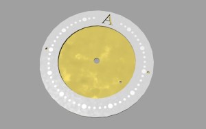
Render of dial

Render of dial


I do a quick mock up on the computer, with a simple silver register ring with different coloured luminous dots, an A at 12 o’clock (for Ashton, I tried using a T but it looked too much like the old Tissot logo), and a reticulated gold centre.

Reticulation is a method of treating the metal by heating and pickling the metal until there is a distinctive difference in the outer layer of the metal to the inside, then heating it to almost melting point, at which time the metal on the inside pulls together, wrinkling the outer layer in a random fashion. While making the entire dial out of this metal would be almost illegible, having the centre made of it will create a nice colour difference from all of the grey and black of the case and register ring.


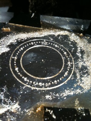
Cutting the register ring

Cutting the register ring


I cut the ring out of a solid piece of silver, with the dots and A pre-engraved, though still needing a little clean up.

Register ring ready for cleaning up

Register ring ready for cleaning up

The register ring is satin finished in the lathe, and all of the holes are tapered a bit to allow the luminous material to hold in better.

Register ring cleaned up and satin finished

Register ring cleaned up and satin finished


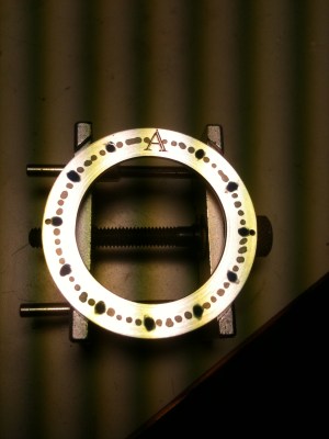
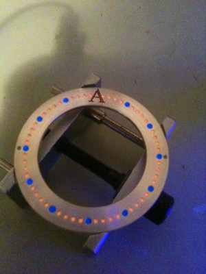
I have a number of luminous compounds, and want to use a blue for the hour markers and orange for all of the minute markers, though these colours are only visible when dark, or under an ultraviolet light. I decide to colour the blue luminous with a blue ink, so that even normally the markers are blue as well. to find a suitable binder or glue to stick the luminous material to the dial takes quite a few attempts, some of them shrink, some are too runny, and others form a putty like substance.. Eventually I get one that sticks to the holes and retains its shape, while still being luminous enough to be visible after dark.

Luminous material in place, but needing to be cut back a bit

Luminous material in place, but needing to be cut back a bit


Register ring cleaned up and under UV

Register ring cleaned up and under UV


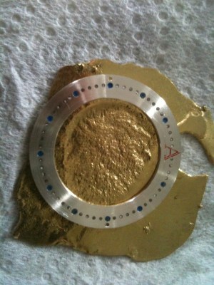
I make a piece of reticulated gold, cut a hole for the centre of the dial and also an outline matching the register ring.

Register ring on rough piece of gold

Register ring on rough piece of gold


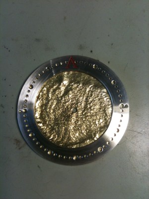
Gold & silver, pre-luminous

Gold & silver, pre-luminous

Balancing Act Thursday, Oct 6 2011 


Now that the majority of the components are playing nicely together, it’s time to get this machine to tick! The most difficult part of this operation is removing the balance from the old bridge, and transferring it to a new bridge without damaging the hairspring or the small parts on the bridge itself.

Part of the reason for this is that ETA now use their own method of holding the balance to the rest of the watch, this is done with a specially shaped stud, held in tension between a “fork” of metal, this in comparison to the traditional method of a cylindrical or semi-cylndrical stud, held in place with a small screw. The ETA method is more efficient in that the height of the stud is set permanently, and is non-adjustable, but usually requires the purchase of specialised (expensive) tools to do otherwise straightforward operations. While my method is definitely not the recommended method, it works most of the time.. With a quick flick of a screwdriver the balance assembly is free from the old bridge.

The components needed are removed from the old bridge and placed on to the new, and not too surprisingly I can already see some issues.. the first being that the seating for the regulator assembly is a little high, which some quick filing fixes. The balance is fitted to the stud holder, (noting that the hairspring will have to be rotated at some point).

I place the complete assembly into the movement, and try and wiggle the balance wheel into position. No amount of cajoling, tapping or swearing works, as the balance wheel is trying to occupy the same space as one of the train wheels.. Not happy..

The options I have at this point are to adjust the position of the train wheels, re-machine all the plates and hope the next iteration has everything in the right place, make a new balance wheel, or fit the rest of the components to the watch (remainder of the winding mechanism), decorate a base 6498 and case that.

The first option was removed from my choices by simply not having the metal needed to complete another full set of plates, combined with the possibility of something still not working and my deadline rushing up..

The second option while briefly attractive, would require some items for my lathe that I don’t own, and some stock material suitable.

The third option it is!  So the things I need to do while reduced is still fairly significant.

Barrels of fun… Monday, Sep 5 2011 

Working backwards in the watch I now need to test that the barrel will play with the rest of the watch and provide the power to keep it going.

I size the hole in the bridge and mainplate, drop the barrel in, and place the bridge on top. The teeth of the barrel are way to tight against the centre wheel, as this is about 2 weeks before heading to Switzerland, I decide that while I need to adjust the model to decrease the engagement of the wheels, in this case I will adjust the barrel, in the hopes that I will be able to have a running movement.

Barrel Bridge in Position

Barrel Bridge in Position

Barrel Bridge in Position 2

Barrel Bridge in Position 2


I have also noted that the barrel bridge is still not thick enough, so that if the movement is turned upside down, the lower pivot will fall out completely, to temporarily solve this, I will fit a bush to the bridge, that will stick out far enough to stop this happening.


To adjust the barrel I use an antique device called a “topping tool” or “rounding up tool” originally used when wheels were not always perfect, or if they had been stretched during a repair. What this tool does, is to re-shape the teeth to the correct profile, and in my case reduce the diameter of the overall wheel while doing so. This does not work perfectly, especially with modern watches, but for the sake of 20 or so minutes work, is worth trying.

Topping Tool and other bits and pieces

Topping Tool and other bits and pieces


With the teeth reduced sufficiently, the barrel drives the centre wheel, not as smooth as it should be, but it turns!


Back to Pallets


I test fit the pallet bridge on the mainplate, and after adjusting holes in the bridge to try and get it located correctly, realise it will be much easier to just make a new bridge, the basic design is 5 holes with the banking sections (this limits the movement of the pallet fork, on older watches there are 2 pins that fulfil this function).


Off to the computer, and an hour or so later I have 2 bridges cut out (a spare is always handy) I size all of the holes, fit the jewel and steady pins into the bridge and place it onto the mainplate.. Everything lines up, with some minor adjustment to the profile, I am able to work the escapement with some pressure on the barrel. Everything is looking good!


Wind me up


With things looking like I might meet my deadline, I move to a couple of (seemingly) minor components, The ratchet wheel and click, these 2 parts prevent the watch from unwinding all at once. First the ratchet wheel is test fitted on the barrel, with a couple of small modifications due to machining artefacts (leftovers) the ratchet wheel is able to turn freely. The click is similar, and a small hole is drilled by hand into the barrel bridge to accommodate the click spring in the correct place. Turning the ratchet wheel by hand, the click works happily. With some more adjustments, the train bridge is put back in place (I hadn’t noticed that the click would try and occupy the same space as the train bridge, but a file soon sorted that out). Using a screwdriver, the ratchet wheel is wound without the pallet fork in, and the train turns relatively freely, some minor tweaks to wheel locations, and the wheels would be as happy as they were in the original movement.  With the pallet fork placed in, and wiggled back and forth, the train unlocks just like a real watch!!


Success.. almost… Wednesday, Jul 27 2011 

Escapement

As I have already determined that I will need to re-machine the plates, I decide to check the escapement components as well, as I don’t want to machine new plates then find problems that I could correct now. The escape wheel won’t be going anywhere, so I focus on the pallet fork and pallet bridge, I am using the pallet bridge directly from the base movement, as it is one part less that I have to machine. I thread the holes for the screws, and fit the bridge, or try to.. the holes for the screws and steady pins do not line up quite right, with some alteration I manage to get the bridge down but the pallet fork is siting at quite an angle, unable to engage with the escape wheel.. Oops.. I figure that by moving the holes for the bridge half a millimetre all will line up nicely and add it to the list of adjustments to be made.
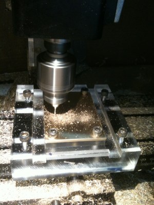
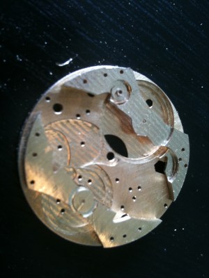
Back to the drawing board….

Determined to get a working movement happening, I return to the computer to check what I’ve done wrong, and to also make some modifications to the design based on my initial observations.

I check the distances that I measured between wheels against those in my computer model, and also the wheel models. I can see (now that I know theres a problem) fairly fast that the wheels are not in the right spot, I adjust the model, moving the 3rd wheel 5/100 of a millimetre, and make sure that the wheel models are now overlapping (representing the teeth meshing together). All appears to be ok, I also add some thickness to the barrel bridge, corrected the placement of the balance bridge components, and adjusted the position of the pallet bridge.

At this point I also make some modifications to the milling program to use a larger milling cutter to do initial cutting (roughing out) followed by a smaller cutter for fine details, in a simulation this will reduce the machining time of the mainplate significantly (from 6 hours to 3) and reduce the chance of breaking the small milling cutter also.

Then back to the milling machine…

I re-machine a complete set of mainplate and bridges (much faster to type than to do) and begin the process of sizing all of the holes and fitting all of the jewels and steady pins again. In my haste I notice (when I go to fit the jewel) that the escape wheel jewel drops though the plate, I check my chart of jewel sizes.. and I’ve read the wrong line.. rather than machine a new plate, I quickly turn a bush to press into the plate that will then have the jewel pressed into it. All good!

I sit the wheels on to the mainplate, and this time everything already seems to be sitting much better..

I fit the train bridge, and wiggle the centre wheel with my finger… The escape wheel spins!!  one part working, just a few to go…


On The Case! Sunday, Jun 12 2011 


While having a movement is great, it really needs somewhere to live, so I started down the path of designing a home for my little brass machine.

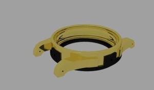
My main criteria for the case is that it adequately protects and allows good viewing of the movement, and wears comfortably.. ideally some water resistance would be nice. I have taken some cues from an industrial context, and made the case quite solid, especially on the case horns (where the band attaches) as this is quite often where cases are damaged and need re-finishing.  I also have designed the case with rapid prototyping in mind, this way I can have the case made in a variety of materials, and even do combinations, for my renders I used a gold case with an ABS plastic case back, but silver or bronze is also quite a possibility.


Render of case side

Render of Case in Gold & ABS plastic


Side note on Rapid Prototyping:


This process, also called “3D printing” is where a model is built layer by layer using a combination of a material and also a “filler” that is placed anywhere there would be a void. Once the model is finished, the filler material is quite often just blown away with compressed air, leaving the finished piece.


Over recent years, the materials able to be used in this process have become quite varied, from a brittle yet very detailed wax, which is able to be used for casting in precious metals, to a stainless steel based powder that can be sintered into a solid steel object, though the minimum thickness of the steel is about 1-2mm vs .1mm for the wax. A variety of plastics can also be “printed” including ABS plastics which are quite strong and durable.


To secure the case main and case back I plan on using 4 bolts or screws, inserted from the sides, top and bottom of the case.

The front crystal is going to plexiglass (plastic) to begin with, as this will show how many times I hit the case on the front, as plexi marks easily,  yet doesn’t shatter, I will look into fitting a domed sapphire crystal when I find a supplier at a reasonable cost.

The rear crystal will be a mineral crystal to begin with to be replaced with sapphire at some point.

While getting quotes to have the case made in either wax or ABS plastic, I decided to mill a prototype of the front of the case, just to see if it looked at least partly ok, the only issue I still have is that the watch is fairly large.

Milling the Prototype case

Milling the Prototype case 2


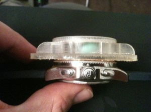
The case measures 60mm long, and 44mm wide (definitely not a small watch by any means)


Height comparison with Breitling B-1

While getting quotes for the rapid prototyping I came across a company that could machine my case instead from solid metal, so I also obtained a quote for this service.

When the quotes came in, there was not a lot of difference in price between getting the case machined in steel, or made in a plastic or wax, plus the lead time required was not too long. The go-ahead was given and the process started.


30th December – Start My Engines… Sunday, May 22 2011 

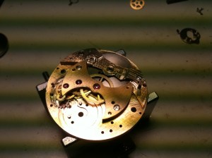
I started machining as soon as possible, a process of around 8 hours solid. only to find that I had gotten confused when translating my measurements to the computer, because of this the recess that holds the barrel was machined too deep, this has the effect of not leaving enough material for the centre wheel jewel to seat into, and also removing some material around the setting mechanism.. Not good!

Re-working the machining file and tooling up, I re-made the mainplate, This time the alignment between the front and back was off by about 0.5mm, as was the next one, so I finally figured out a method of lining the front and back of the plate up a bit more effectively. I had been relying on using locating holes in each plate lining up with matching holes in a perspex machining jig.

Perspex Jig to hold plates


The new method involves moving a tapered point inside holes in the plate, adjusting slightly, moving to the next hole and so on, until the point is in the centre of all of the holes. Using this method I machined a set of both mainplate and bridges, all appearing to line up within about 1/10th of a mm.

Raw Train Bridge

Mainplate with barrel and balance bridges

I enlarged all of the bridge hole to the proper sizes for all of the jewels, and fitted them all, then did the same for the train bridge. As I test fitted the train wheels it became apparent that something was not quite right, the 4th wheel with the extended pivot for the small seconds hand would no longer fit through the jewel.  After a quick modification and removal of the long pivot, the wheel would fit. Success!!  Steady pins were added to the train wheel bridge so that it would locate in the correct place every time, taking a cue from Peter Speake-Marin I made these pins tapered, so that as the bridge is lowered it fits neater than if they had been completely parallel.

Mainplate with train bridge fitted

Short lived success though.. after placing the rest of the wheels in to the plates the first 2 wheels in the train mesh a little tightly and the 3rd and 4th wheel do not touch at all!  and to top everything off, I’ve run out of brass to mill plates out of and most people are closed over Christmas / New Year.. so at least this gives me some time to work on the dial and hands…

Things you discover when remodelling a watch movement… Sunday, May 8 2011 

Some interesting points.

While I tried to reduce the overall diameter of the movement under the original, it ended up being very close to the original (this was actually a good thing – will explain in a later post)

The original movement uses large (2mm outside diameter) jewels on the bridge side of the movement, and small (1mm outside diameter) jewels on the dial side of the movement, while this has little functional effect, I prefer to have nice beefy jewels on both sides, as it looks much better, and I had a few spare due to the number of movements I had bought.

Dial Side, showing jewel sizesBridge side, showing Larger jewel sizes

Bridge side, showing Larger jewel sizes

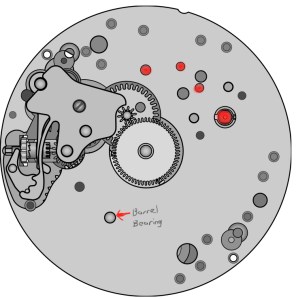
The original movement uses the manipulate itself as the lower bearing for the barrel and this is a common wear point for many watches (looking at you Seiko.. and early Rolex as well..) I decided to replace this with a jewel (coincidentally the same pivot diameter as the centre wheel) although I haven’t found a jewel large enough for the upper bearing, I will use a bronze bushing for this, which at least can be easily replaced.

Because of the way I had moved the train around, the setting mechanism would no longer fit in the orientation that it was originally used, luckily (again) the 6497 and 6498 use a mirror image of the setting mechanism, and with some juggling, I found a spot where everything appeared to play nicely.


Handy!

Over the Christmas break I also caught up with a number of friends, amongst whom is a retired engineer who’s father was a watchmaker, he showed me an old electric car clock, and the hands immediately took my fancy, I knew straight away that these shapes had to end up on my watch.

Neat hands, stylish too!

Next Page »